


Page 60 - LIT-18626-15-20
P. 60
UF3X16E0.book  Page 48  Wednesday, July 17, 2024  9:11 AM


                        Instrument operation

                        EJU46643                              When the warning symbol is displayed, select
                                      Display
                                                              the warning symbol to  display the warning
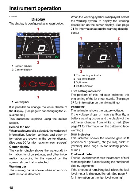
                        The display is configured as shown below.
                                                              description on the center display. (See page
                                         1                    71 for information about the warning descrip-
                                                              tions.)
                                    NW    N   NE                   1                      2
                                                  F

                                                                          NW   N   NE
                                                                                        F
                                              MPH
                                            RPM
                                                    E
                                   OFF            PM
                              12.7v
                                                                                   MPH
                                         2                                        RPM     E
                          1 Screen tab bar                              OFF            PM
                                                                   12.7v
                          2 Center display
                                                                   3                      4
                                                               1 Trim setting indicator
                                                               2 Fuel level meter
                                                               3 Voltmeter
                                                               4 Shift indicator
                                                              Trim setting indicator
                                                              The position of this indicator  indicates the
                                         1
                                                              trim setting of the jet thrust nozzle. (See page
                          1 Warning bar                       37 for information on the trim setting.)
                        It is possible to change the visual theme of  Voltmeter
                        the display. (See page 61 for changing the vi-  The voltmeter shows the battery voltage.
                        sual theme.)                          If  the voltage  drops  or rises significantly, a
                        This document explains using  the default  battery warning occurs and the display of the
                        screen.                               voltmeter changes  from white to red. (See
                        Screen tab bar                        page 71 for information on the battery voltage
                        When each symbol is selected, the watercraft  warning.)
                        information, function settings, and other in-  Shift indicator
                        formation  are shown in  the center display.  This indicator shows the reverse gate shift
                        (See page 50 for information on each screen.)  positions: “F” (forward), “N” (neutral), and “R”
                        Center display                        (reverse).  (See page 35  for shifting proce-
                        The center display shows the watercraft in-  dures.)
                        formation, function settings, and other infor-  Fuel level meter
                        mation according  to the symbol  on the  The fuel level meter shows the amount of fuel
                        screen tab bar that is selected.      remaining in the fuel tank using the number of
                        Warning bar                           display segments.
                        The warning bar is shown when an error or  If the amount of remaining fuel is low, the fuel
                        malfunction is detected.              level meter is displayed in red. (See page 71
                                                              for information on the fuel level warning.)


                        48

