


Page 62 - LIT-18626-15-27
P. 62
UF5S10E0.book  Page 52  Monday, September 23, 2024  2:13 PM


                        Instrument operation


                                         1                    Push the “OK” button of the touchpad control
                                                              when  the warning symbol is displayed  to
                                                              show the warning  description, error  code,
                                                              and other information in the center display.
                                                              (See page 56 for information about the warn-
                                       RPM x1000
                                                              ing descriptions.)
                                                                      1                2
                                               MPH
                            14.3v
                                         2
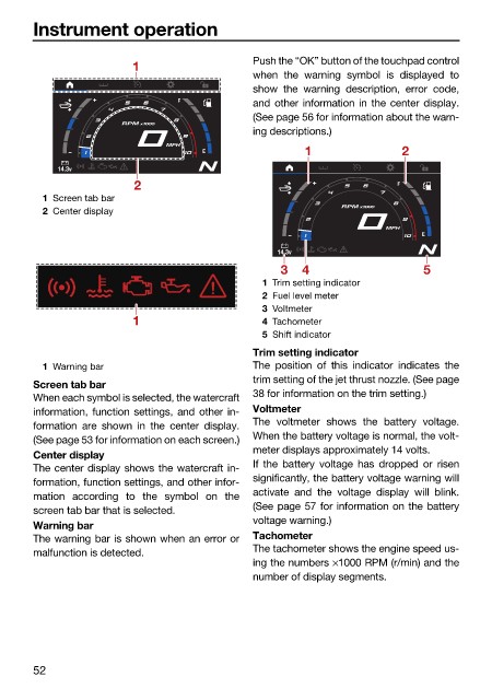
                          1 Screen tab bar
                                                                             RPM x1000
                          2 Center display
                                                                                    MPH

                                                                  14.3v
                                                                  3   4                    5
                                                               1 Trim setting indicator
                                                               2 Fuel level meter
                                                               3 Voltmeter
                                         1                     4 Tachometer
                                                               5 Shift indicator
                                                              Trim setting indicator
                          1 Warning bar                       The position of  this indicator  indicates  the
                                                              trim setting of the jet thrust nozzle. (See page
                        Screen tab bar
                                                              38 for information on the trim setting.)
                        When each symbol is selected, the watercraft
                        information, function settings, and other in-  Voltmeter
                                                              The voltmeter shows the battery voltage.
                        formation are shown  in the center display.
                                                              When the battery voltage is normal, the volt-
                        (See page 53 for information on each screen.)
                                                              meter displays approximately 14 volts.
                        Center display
                                                              If the battery voltage has dropped or  risen
                        The center display shows the watercraft in-
                                                              significantly, the battery voltage warning will
                        formation, function settings, and other infor-
                                                              activate and the voltage display will blink.
                        mation  according  to the symbol on the
                                                              (See page 57 for information on the battery
                        screen tab bar that is selected.
                                                              voltage warning.)
                        Warning bar
                        The warning bar is shown when an error or  Tachometer
                                                              The tachometer shows the engine speed us-
                        malfunction is detected.
                                                              ing the numbers ×1000 RPM (r/min) and the
                                                              number of display segments.


                        52

